
On order


PWK650
4,400,00 zł gross

FIVESTARS
48,00 zł gross

FIVESTARS
45,00 zł gross
FIVESTARS
70,00 zł gross
AUTOIRANGA
5,580,00 zł gross
INNE
20,00 zł gross
SATRA
61,00 zł gross
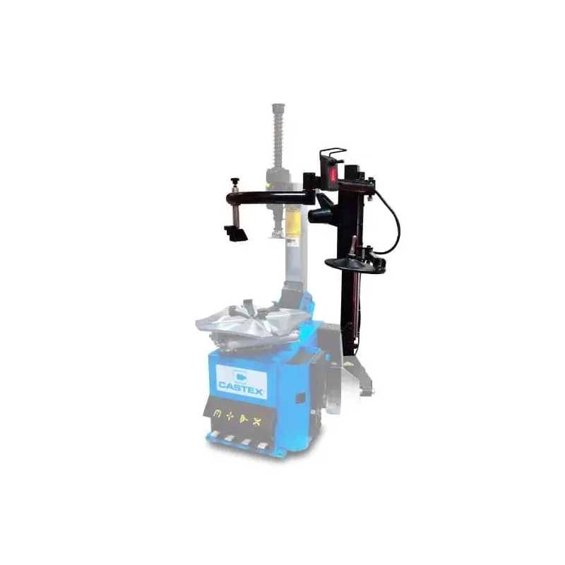
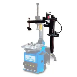
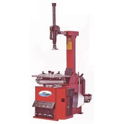
Auxiliary arm for the CASC505 automatic tyre changer, code CAM-113 505 Auxiliary arm for the CASC505 tyre changer – assists in applying pressure to the tyre during the removal and fitting of tyres, including standard, low-profile and run-flat tyres. This auxiliary arm, which is an optional extra, has been designed to facilitate the fitting and removal of tyres, particularly low-profile tyres, C-type reinforced tyres and run-flat tyres. CONSTRUCTION AND INSTALLATION Install stabilising foot C onto arm body A. Once the arm is installed on the machine, use nut B to secure the foot. Disconnect the tyre changer from the air supply and the mains power supply. Position arm body A on the tyre changer housing M, aligning the mounting holes in both components. Screw the arm body to the horizontal surface of the tyre changer housing using screws F (M10x35mm), using spring washers E and flat washers D. Do not tighten the screws fully; leave a gap between the bodies of the components being screwed together. Screw the arm body to the vertical surface of the mounting bracket housing using screws G (M10x35mm), using spring washers H and flat washers I. Do not tighten the screws fully; leave a gap between the bodies of the fastened components. Insert spacer plate J between the arm body and the mounting frame housing. Tighten all bolts. Adjust the position of stabiliser foot C and secure the setting with nut B (M16). Install the three arms B, C and D onto the movable carriage of arm A as shown in the diagram. Install the second section of the double-jointed arm E onto part D as shown in the diagram. Thread the pneumatic hose (8 mm) Q through the hole in the side panel of the machine body into the interior. Open the side cover of the mounting unit and locate the 8mm pneumatic T-piece; the T-piece is situated on the main compressed air supply line and splits the air supply line from the air preparation unit into two separate supply lines for the control pedal assembly and the main arm assembly. Remove the T-piece and replace it with a Z-piece, where the fourth additional connection will be used to connect the auxiliary arm. Connect the pneumatic hose Q to the Z-piece on the tyre changer. Close the side cover of the tyre changer. OPERATION The arm is designed for fitting low-profile tyres, C-type reinforced tyres and run-flat tyres; however, its universal design allows it to work with any type of wheel, thereby significantly facilitating mounting and demounting whilst reducing the risk of damage to the tyre and rim. TYRE REMOVAL Place the wheel on the tyre changer table, ensure that the tyre bead is separated from the rim edge, and apply the external grip. NOTE: Removing and fitting a tyre using the auxiliary arm requires the use of an external rim gripper. This is because the increased range of operation provided by the auxiliary arm can generate additional stresses on the rim and tyre. Using the joystick, lift the entire auxiliary arm above the top surface of the wheel; position the pressure arm with the roller so that the roller is above the sidewall of the tyre, i.e. as close as possible to the rim edge (the roller must not touch the rim edge). Using the control joystick, gradually lower the arm whilst pressing down on the tyre, simultaneously rotating the mounting machine’s work table clockwise. To remove the upper tyre bead, move the mounting head A towards the rim edge. Then, using the auxiliary roller C, press the edge of the tyre so as to slide the mounting spoon B between the mounting head and the tyre bead. Lift the auxiliary roller C and move it to the rest position so that it is not in the working area. Position the tip of the pressure arm E above the side edge of the tyre, opposite the mounting head A. Using joystick D, lower the pressure arm so that the tyre bead is positioned below the rim seating edge. Using the mounting spoon B, pull the tyre bead onto the mounting head. When correctly seated, the bead on the left side of the head should be under the guide rail, and on the right side on the head’s crown. Raise the auxiliary arm so that the clamping arm releases the tyre, and move all working arms out of the work area of the table. Press the Z control pedal; the work table will begin to rotate clockwise, and the mounting head will move the tyre bead over the rim edge. To remove the lower bead, use the turntable. Position the turntable under the tyre so that it does not touch the rim. Press the Z pedal; the work table will begin to rotate. At the same time, use the control joystick to gradually raise the turntable so that it lifts the tyre whilst sliding the tyre bead off the rim’s mounting edge. Once the lower bead of the tyre is completely detached from the rim, proceed to the standard removal procedure using the mounting head and the tyre lever. TYRE FITTING To fit the lower bead of the tyre, apply tyre mounting grease to both tyre beads and, if necessary, to the mounting head. Slide the tyre over the rim so that the mounting head can be moved up to the rim edge. Position the lower bead of the tyre on the mounting head so that the bead on the left side of the head rests on the head’s guide rail, and the bead on the right side is positioned under the head’s main body. Press the Z-table rotation pedal whilst simultaneously pressing the tyre with your hands so that the lower bead gradually moves over the upper rim edge. Continue this action until the lower bead of the tyre is fully seated on the rim. To mount the upper tyre bead, position the bead on the mounting head so that the bead on the left side of the head rests on the head’s slide, and on the right side it is positioned under the head’s headstock. Position the auxiliary roller C above the tyre, as close as possible to the rim edge. The roller must not touch the rim directly. Position the pressure arm E immediately adjacent to the auxiliary roller and adjust its initial position so that it touches the side of the tyre. Using the control joystick D, lower the arm so that both the auxiliary roller and the pressure arm press against the tyre. The tip of the pressure arm should be positioned below the auxiliary roller at a height such that the upper bead of the tyre is below the rim flange. This position of the bead relative to the rim, maintained by the pressure arm, ensures that stress is minimised by keeping the tyre bead in the part of the rim where its diameter is simply the smallest. NOTE: The guide roller and clamping arm must not touch the rim at any stage of tyre fitting. Press the rotation pedal; the work table will begin to rotate along with the wheel. As the guide roller rotates, it will guide the tyre bead below the rim’s mounting edge, and the pressure arm will hold the bead in the area where the rim has the smallest diameter, minimising stress. NOTE If any of the operations begin to proceed incorrectly, stop the tyre mounting process. Lift the control pedal Z; the work table will begin to rotate anti-clockwise. Once the tyre has been loosened, adjust the position of the auxiliary arm and try the fitting again. NOTE: During operation, no one other than the operator must be present in the machine’s working area.

Credit card

Google Pay

Blik

Przelewy 24

Cash on delivery

Paleta DPD
1-2 business days

DPD Pallet COD
1-2 business days

Personal pickup
Processing within 24h
Castex Anna Bednarz
ul. Fordońska 44C 85-719 Bydgoszcz
tel: +48 52 515 64 22


